|
Prepare
for the process by getting five parts trays or boxes. I use the cardboard
flats that sodas are sold in. These are to keep the parts from wandering
off and to keep various components of the machine separate from each other
so that reassembly requires less rummaging. I label my boxes for the (1)
carriage, (2) mainframe, (3) left and (4) right side parts, and (5) carriage
rail/escapement assembly.
How far you disassemble the machine depends on how much restoration you
want to do. In my case, I decided to do a complete reconditioning, including
paint job, so this meant almost total disassembly. If you do not intend
to go that far, disassemble things only as much as necessary to do the
cleaning that is needed and to replace defective parts.
First,
remove the carriage.
Find the right margin stop on the lower right side and slide it completely
off. Then depress the carriage release plunger under the left platen knob,
remove the carriage to the left and set it aside in your "carriage" box.
Tip the machine to gain access to the underside and remove the screws
that hold the cast nameplates on. Put them in your "left" and "right"
boxes, respectively.
Still working under the machine, remove the thumbscrew on the carriage
spring barrel shaft (NOTEit has left hand threads). If the ratchet gear
does not come off by itself, a light tap from a screwdriver handle on
the end of the shaft will knock it loose. The spring barrel can now be
pulled out from the top of the machine and all of these parts can be put
into the "left" box.
The carriage
rail/escapement assembly is removed next.
First, spend a minute looking at how it all goes together. Note the two
hourglass-shaped rockers that support the assembly at the sides. These
will fall away when the assembly is lifted off and it would be nice to
know where they go when you put it together again.
|
|
|
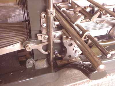
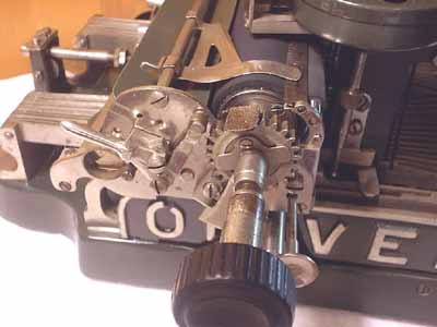
2. Shifting levers on right side
of typewriter
|
Also, study
the various levers and cranks on the right side of the machine that lock
and unlock the carriage when shifting (See Photo 2).
Under the
machine, remove the nut from the end of the screw supporting the sliding-block
for the universal bar, and then turn out the screw and block. Back on
top of the machine, remove the retainer on top of the tail brace roller
at the back of the machine by removing the two side screws. There is no
need to disturb the center adjustment screw yet (Rule of thumbnever disturb
any calibration settings unless you absolutely need to).
Disconnect
the shifting arm below the keyboard by pulling the cotter pin. Next, remove
the L-shaped hold-down retainers at the sides of the type towers. Note
that the left one has its bottom flange pointed out and the right one
has it pointing in.
Finally, remove the lateral alignment rod between the two type towers.
At this point, you can fiddle and juggle the carriage rail/escapement
assembly back and forth and upward, getting the shifting arm off its pin,
and gently freeing the entire assembly and lifting it away. If it hangs
up, just stop, look for the obstruction, and carefully work around it.
Patience will be rewarded. Place the removed assembly and all the little
parts that go with it into your "carriage rail/escapement" box.
Next,
disassemble the key levers and typebars.
Work on one side at a time and place all components into the box for that
side. First, make a chart showing the order of key levers as they pass
through the comb, going from one side of the machine to the other. This
will make reassembly a lot easier later. Then, going to the type tower
of your choice, remove the plated typebar guard and set it aside.
Under the machine, remove the gear on the end of the ribbon shaft. With
the machine right side up, loosen the setscrew on the ribbons shafts
knurled knob and pull the shaft out from the top, noting any washers that
are revealed in the process. Remove the ribbon cup. There will be (fiber)
washers under it too. Remove the four screws holding the two typebar retainers
and typebar rest to the plate on top of the type tower.
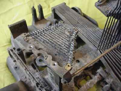 |
| 3.
Note all the dirt that got between and under the typebars. Cleaning
this with the typebars in place would have been impossible. |
 |
| 14.
Key levers and typebars during reassembly. |
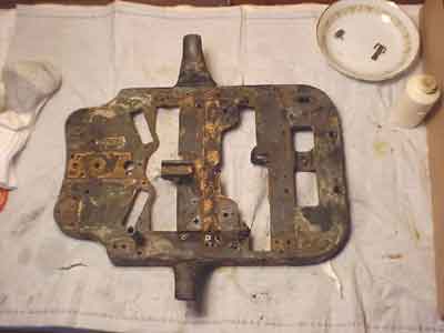 |
| 4.
Frame casting prior to stripping and refinishing |
The typebar
rest (Photo 14) is another detail that differs from later versions of
the model 2 and the model 3.
At this point the typebars will be floating aimlessly above the machine,
so be careful not to whack them. You will also see all the crud and filth
that was hiding below the typebars and in the bearings (See photo 3).
This is why taking all this apart is importantyou would never get it
clean otherwise.
Now, move to the back of the machine and loosen the setscrew holding the
pivot shaft running through the key lever standard (the casting that all
the key levers are hinged to). Remove the spring from the innermost key
lever and pull the shaft out just far enough to free the lever. Carefully
disentangle the lever/typebar combination and lift it free. Now bend the
retaining tab on the key lever just enough to disconnect the typebar arm
from the key lever and set both parts aside. Later models of the Oliver
have a spring-loaded gate here that allows you to separate these parts
more easily. You may be tempted to leave this alone to avoid bending things,
but trying to clean this assembly in one piece risks more damage than
taking it apart. Separating these parts will simplify reassembly later
on as well. Repeat this process for each key lever/typebar combination
for the rest of the side you are working on, continuing to work from the
inside out.
When the last key lever is removed, the rectangular plate with spring
holes in it can be removed from the frame casting (your machine may or
may not have this as a separate piece). Note that the holes are not centrally
locatedthe plate goes in with the line of holes toward the front of the
machine. Follow the same procedure on the other side of the machine.
Now remove
as much as you need to from the mainframe. Even if you are not going for
complete disassembly, everything that is easy to remove should be taken
off to make cleaning easier.
Since I was going to repaint the machine, I took it all apart, leaving
nothing but a really ugly frame casting (See Photo 4).
At the very least, I would remove the tail brace roller at the back of
the machine, the bell and its cast mount, the space bar and the patent
plate under it, the ribbon switch knob and its base plate, the key lever
comb, and the shift lever assembly.
Taking off this latter component involves unscrewing the hinge casting
and shift lock lever from below, removing two link screws from the side
(directly under the vertical travel limiter on the type tower), and then
gingerly maneuvering the whole thing out to the side, bringing the two
springs along with it.
I treated
this shift lever assembly as a separate component for disassembly
and cleaning purposes.
Separate the levers, pedestal, and spring parts, but do not remove or
alter any adjustment settings on the levers. After the parts were processed,
it was reassembled to await insertion into the machine as a complete unit.
I discovered too late that the little "plastic" bushings decorating the
spacebar holes in the frame were SCREWED in. I pried the first one out
and ruined it, and since the second one had a chip out of it anyway, I
had to make replacements. A good source of material for small turned plastic
parts like this is the handle of a cheap screwdriver (Phillips head, since
it goes into a lathe chuck easier). I made two new bushings this way and
they look fine (See Photo 5).
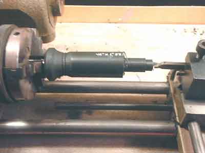 |
| 5.
Making two new space bar hole bushings from a screwdriver handle |
If you
dont have a lathe, an electric drill and a file may do it. Better yet,
dont mess up the parts in the first place!
Turn the
machine over and disassemble as many of the bottom components as you need
to, working logically by removing the most accessible parts first and
then those lying beneath.
There are a variety of screws holding everything together. Take notes,
if necessary, to remember which kind of screw goes where. Removing screws
sounds like a straightforward process, but 100-year-old screws can sometimes
be cranky, especially if they have already been mistreated by someone
else. Minimize problems by saturating the screws with something like Liquid
Wrench or kerosene and let the machine stand overnight. Then make sure
your screwdriver fits the screw heads perfectly.
I have modified a number of screwdrivers over the years by filing and
grinding so that now I have one that pretty much suits any task. In spite
of such efforts, though, you will eventually ruin a screw slot. Your choices
then are to leave the item alone and work around it, or to drill out the
screw and replace it. I ended up taking both of these routes on this project.
Two screws that I thought absolutely needed to come out were drilled,
and another assembly that was giving me trouble was left alone.
Replacement screws can often be scrounged from your parts machine collection,
and if that fails, hobby shops usually have interesting selections of
small, odd screws not found in hardware stores. In addition to the photos,
make your own drawings of how things are arranged whenever you have the
slightest doubt. This kind of major disassembly can be an intimidating
process, especially the first time you do it, and you may wonder if youll
ever get it all back together again, but a careful, methodical approach
and attention to detail is the key. Keep things organized, dont try to
do it all at once, and when you get tired or frustrated, just walk away,
do something else, and come back later.
If you are
going disassemble the base all the way in order to repaint it, the last
thing to come off is the type tower pedestal casting, secured by four
screws on the underside. Beneath this unit are two shafts that carry carriage-locking
motion from the left to the right side of the machine. Disassemble these
as well. Put all pieces from this exercise into the "mainframe" box. I
left the typebar mounting plates on top of the pedestals (these screws
were immovable) and simply masked these parts for repainting.
Spraying paint stripper on them wont hurt them, and in fact stripper
makes it a lot easier to get 100-year-old crud off of unpainted parts.
In fact, I used it specifically for this purpose in a number of places.
As with the main body of the machine, disassemble only as much of the
carriage as needed to be able to clean and repair the component thoroughly.
At a minimum, I recommend removing (in order):
- The paper bail and associated sliding fingers (one screw on each side)
- The line spacing lever/roller and spring on the left side (watch for
the little spring-loaded detent button to fly out from behind it when
disassembling)
- The paper table (two small screws on each side, one of them under the
line space lever)
- The platen and platen shaft (remove setscrews and pull shaft out from
the left)
- The front double feed roller assembly and paper scale (one big screw
on each side) This last assembly will fall apart when removed from the
confines of the carriage, so examine it carefully beforehand to see how
it goes back together.
If you want
to get the lower feed roller out of what remains of this assembly, you
will need to remove one more screw to get one of the end pieces off. See
Photos 7 and 8 for details of carriage construction.
 |
| 7.
Left end of carriage showing positions of controls |
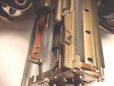 |
| 8.
Right end of carriage from below showing strap, clip, and rail wheel |
The large
bottom feed roller may not need removing unless you intend to get it recovered
or if you want to unscrew the rear carriage support wheel. If you want
it out, remove the two screws holding one of the two bearing blocks in
place. I also removed the line-advance device with the gear segment on
it. This needs to come out if you want to get the left front support wheel
off. I took all three support wheels off to make sure their bearings got
thoroughly cleaned.
IMPORTANTWhile
the rear carriage support wheel is laterally free floating, the two front
ones are adjustable for minimum play to keep the carriage stable on its
rails. These two wheels (on my machine, at least) are asymmetrical, with
a thicker edge on one side than on the other. How these wheels are installed
will influence the front-back position of the carriage, so note the original
orientation and put them back the same way. If you have funny looking
print later on, with the top and bottom of the letters having different
density, this may be the problem. I also removed the carriage release
plunger and its sliding plate.
I loosened, but did not remove, screws securing the left carriage end
plate so that I could remove the painted paper guide in front of the paper
table since this part was going to be repainted. Depending on levels of
wear and filth, you may want to remove more parts or stop here.
Decision
Time:
Now that you have the machine disassembled as far as you have chosen to
go, it is time to decide whether you want to get the platen and feed rollers
recovered with new rubber. New rubber is not necessary, of course, unless
the existing rubber parts are so badly deteriorated that they ruin the
machines appearance, or unless you want to do a working restoration so
you can use the machine to type with.
Disassembly quickly gives you a clue as to how practical a working restoration
will be. A lot of broken parts or evidence of a lot of wear and tear (rounded-off
teeth on the escapement wheel is a bad sign) may lead you to conclude
that the machine is a candidate for static display only, and not worth
the extra expenditure. On the other hand, a good mechanism on the inside
and good looks on the outside may convince you that you want to do more
than just visually admire your work when you are done.
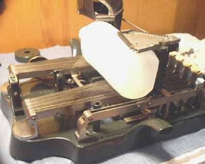
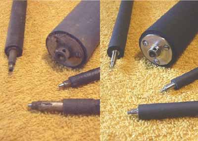 |
| 9.
Platen and feed rollers before and after recovering |
If you do
decide to get the platen and feed rollers recovered, now is the time to
send these parts off to your favorite recovering shop (I use Ames Supply
Company, in Downers Grove, Ill). By the time you get the rest of the parts
cleaned and ready to be put back together, the new rubber will be back,
waiting to be included in the reassembly process. If new rubber is not
in plan, clean up the platen and rollers as best you can and set them
aside for reassembly. I generally go around a platen I do not intend to
replace with fine sandpaper to give it a smooth, consistent texture and
color and let it go at that. My Oliver 2 platen was not particularly ugly,
but the feed rollers were beyond help (See Photo 9). I decided to go for
new rubber all around.
And now
it's time for
Cleaning and Refurbishing:
|