|
|
|
Generally
speaking, put things back together in the reverse of the order you used
to take them apart.
Attach the
cranks and levers on the right side of the pedestal casting, noting their
proper relationships (See Photo 2 again). Adjust the little concentric
screw arrangements with the itty-bitty springs so that the levers rest
naturally at least 180 degrees back from their eventual position. You
have to attach the shift lever assembly on the left side before you can
secure the left-hand levers into their final positions. Well come back
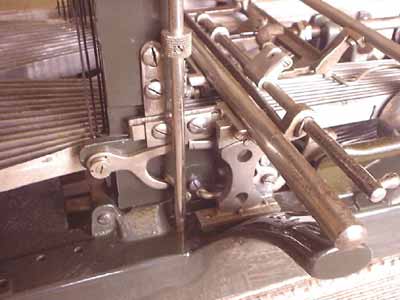
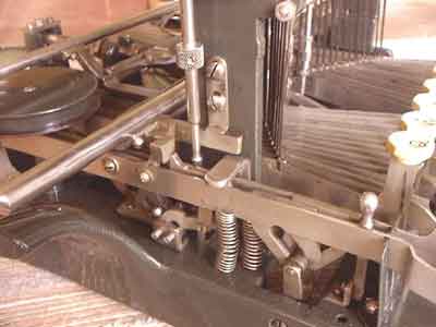
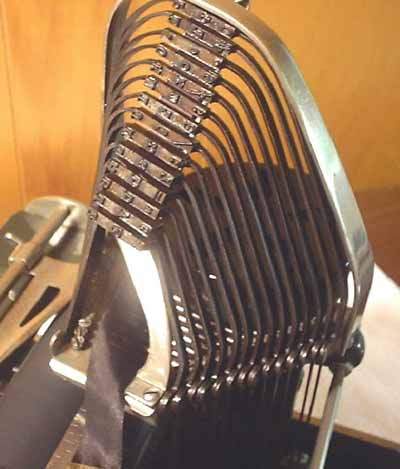
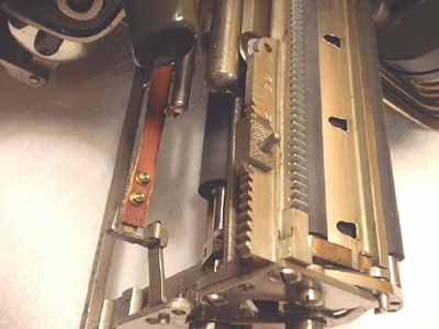
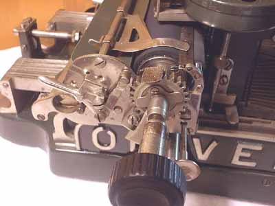
to that. IMPORTANT: Adjust these levers on their cross shafts so that the top arms of the shift lockers on the right side are close to their eventual position but still somewhat ABOVE the horizontal. When the carriage rail assembly is added later, it will push these arms down on their springs to a nearly horizontal position (See Photo 2 again). If they are below horizontal to begin with, they will not work properly, and after the carriage rail assembly is in position, it will be almost impossible to access the screws to readjust them. Depress one of the shift levers and slide the shift lock lever with its mounting angle into position. Secure with its screw from the bottom of the machine (See Photo 13 for left-side shift lever detail). With the base reassembled, it is time to move on to the key lever and typebar assemblies. The order in which you do things here can make the difference between a relatively easy job and endless frustration. Doing one side at a time, first install the key levers, working from the outside in so that you can attach the springs easily. Push the shaft into the key lever standard at the back of the machine one slot at a time as the levers are positioned. The springs, of course, will leave the levers standing at a steep angle. After all have been installed, push them down into their respective comb slots and then wedge some kind of object on top of them and under the typebar plate to hold them down. I found a rubbing alcohol bottle to be just the right size (See Photo 14). This lets you install the typebars without having to fight the springs. Remember to tighten the setscrew on the key lever standard when you are done. Next, install the typebars, again working from the outside in, opening the gates on the key levers with a small screwdriver as needed, and then bending the gates closed again with needle nosed pliers. When all the typebars are in position, screw the retainers down onto the mounting plate. Remember to position the foot of the typebar rest and the little brass trim piece over the front inside hole of the typebar retainer first. Tighten this last screw only minimally for the time being. Attach the ribbon cup (remember the washers that go under it), and then drop the ribbon shaft into place, positioning the washer and knurled knob as you go. Dont worry about the gear on the bottom of the shaft just yet. Now, replace the arched typebar guard. Last, insert the big screw with its felt washer and plastic bushing through the top of the typebar guard and then finish tightening the screw on the bottom end of the typebar rest (See Photo 15 for type tower details). Repeat this whole process on the other side of the machine. Its starting to look like a typewriter again, isnt it! Now that both type towers are back together, the machine will again be stable when flipped on its back. It is safe to rest it upside down on its type tower guards. Just dont apply undue forces. (Rule of thumbIf you have to use force, youre probably not doing it right)! With the
machine upside down, attach the gears to the ends of the ribbon shafts.
Now adjust the spring that holds the ribbon switch lever so that the gears
engage evenly on both sides when the switch is thrown. With the key levers
back in place it is now time to reassemble and replace the spring barrel.
I took mine completely apart because something heavy had apparently been
dropped on the machine at some point and the barrel shaft (along with
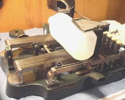
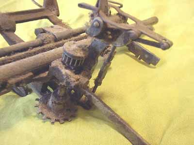
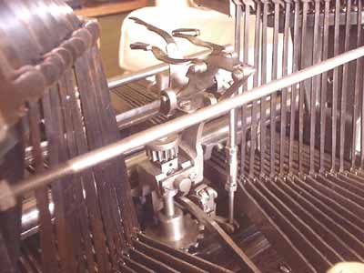
the rear carriage rail) was bent. Next comes the carriage rail/escapement assembly. Considering how filthy it was to begin with (See Photo 16), I completely disassembled it EXCEPT for the calibration nuts on the tail brace, the shift calibrations on the sides, and parts making up the ribbon vibrator that were pressed together. This is one of those cases where spraying the parts with paint stripper made the cleanup a lot easier. After about 20 minutes of soaking, 100 years of gross crud came off of these small, intricate parts with amazing ease (See Photo 17). In reassembling this component, I purposely flipped the two carriage rails 180 degrees. This moved some visible signs of corrosion down out of sight and also presented fresh bearing surfaces to the carriage wheels. Juggle the
complete assembly back down into position. You have to keep your eye on
about four things at once while you do it. Make sure the shifting arm
goes back onto its activating lever under the keyboard. Check to see that
the slotted escapement activator arm under the back of the assembly does
not tangle with anything on its way in. See that the left and right shift
positioning tabs interact properly with the shift levers on the left and
the levers on the right typebar pedestal. Reassembling the carriage is fairly straightforward. Just reverse the process of disassembly and look again at Photos 7 and 8 for how things are supposed to look when you are done. Now FINALLY, you can slide the carriage back onto its rails and see if it all works. As you are doing this, check to see that the carriage strap clip engages properly. If it doesnt, bend either the clip or the hanger on the carriage until it works reliably. In case your machine didnt come with its clip, see Photo 8 to see what one looks like. And now, the finishing touch: |