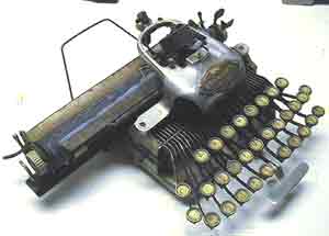
The Blickensderfer 5/6
Guidelines for disassembly by Rob Blickensderfer - 3
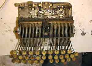
D DISASSEMBLY OF HEAD
Remove the paper guides, and associated springs and parts. Often, the printwheel is frozen to its shaft. If so, it can be freed after the shaft is removed. Sometimes, the shaft is frozen in its bearing. This is more serious as it must be freed to be removed. Soak the bearing with penetrating oil. Then
1. Remove the nut (or 2 nuts) from the lower end of the shaft.
2. Remove the shift slider bracket from the end of the shaft. On some machines this is screwed to the shaft, therefore, the shaft must be rotateed to unscrew it.
3. Slide the shaft out. This may require some gentle twisting and pulling. After the shaft is out, if the typewheel is still stuck to the shaft, clamp the shaft (careful not to bend it) and torque the typewheel, by hand, until it is free. If the typewheel shaft is bent (yes, it does happen), it should be straightened to within 0.001" using a lathe and dial indicator.
4. The bevel-gear-and-indexing-wheel assembly can be removed. A groove on the lower end of the bevel gear fits into a shoulder on the shaft bearing that retains the bevel gear assembly. To remove the bevel gear assembly, push both segment gears, as well as the bevel gear assembly and bearing, downward toward the platen. Slide the bevel gear assembly upward to disengage it from the retaining shoulder. Then pull the bevel gear assembly away from the segment gears. Reassambly is a bit tricky: The segment gears must be lowered about halfway, both the same, toward the platen. The bearing must be lowered a little bit farther (it pivots independently of the segment gears). The bevel gear assembly must be rotated into its neutral position, then engaged exactly in the center between the segment gears, ie, equal number of teeth on the segment gears above and below each bevel gear. Then, pivot the bearing upwards to engage the retaining shoulder into the groove on the bevel gear.
5. Further disassembly, eg removing the segment gears, is not normally required. But if they are frozen, the shaft for the segment gear assembly can be freed and/or removed. Losen the two setscrews, one near each end of shaft, on the front of the head casting. The shaft can be freed by tapping either end of the shaft with a hammer on a drift pin. Removal of the shaft allows the rest of the parts to be removed. Usually however, just loosening the shaft allows the segment gears and other parts to be freed and lubricated.
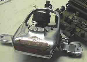
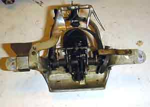
E DISASSEMBLY OF MAIN FRAME
To remove slider (the slider that actuates the escapement):
1. Remove escapement arms
2. Remove bottom protector plate, 2 screws 3
. Remove long coil spring from slider
4. Remove vertical finger from slider, 2 screws
5. Remove spring on space bar. This spring is next to slider, on right hand side. It is stiffer (larger diam wire) than keylever springs, but of same configuration.
6. Remove the keylever retainer plate (long narrow plate that holds keylever ends in place), on bottom of machine, 3 screws.
7. Lift out space bar and arm (machine right side up)
8. Slide out the slider, to the rear.
9. Lift roller out, from the top.